The Discovery Cube Manufacturing Report

Kellen Chow
Elizabeth Hohenstein
Eric Totong
Rapid Prototyping 39-245 (B)
March 2, 2010
Original Design
The original toy design for The Discovery Cube is intended for children under the age of about 2. Each of the six sides of the cube has a different activity for the child to explore, engaging as many different senses as possible (sight, sound, etc.). The cube is made out of non-toxic plastic and has rubber bumpers on each corner and sharp surface to minimize injury. The cube contains no small parts that can fall off and cause choking. Here is the original design website.Design Process
The first step after drawing the initial design was to make a preliminary CAD model. Our CAD model was done in SolidWorks. Each side was designed so that the final product (when assembled) measured out to be a 10"x10"x10" cube. Here is a picture of the original CAD design. Our intention was to make the cube out of non-toxic plastic that was one inch thick and have the sides screwed or glued together. Each side would have a different activity outlined in the design (see the original design website).
After consulting with Larry Hayhurst in the Chemical Engineering Machine Shop we learned that the laser cutter in the shop only cuts plastics with a thickness of 0.2" or less. We decided to change our material to clear acrylic with a thickness of 0.1" and glue the pieces together to form the cube. We also decided to change the design so that instead of activities on each side there would be different kinds of material on each side. This would make it easier to manufacture (the thin acrylic wouldn't likely be able to have the activities we had planned originally) and give us more experience with the laser cutter. Our final design was the same size cube (10"x10"x10") but each face would be 0.2" thick. We would make each face by sticking two acrylic sheets together. The top sheet on the face would have the laser-cut shape and the bottom sheet would be a solid rectangle. We planned to make the cube with six of these double-layer pieces and connect them with acrylic solvent. We ordered fourteen 12"x12"x0.1" acrylic sheets from McMaster Carr (www.mcmaster.com).
We redesigned the cube in AutoCAD to match the specifications required by the laser cutter. The laser cutter uses.dxf files, which is a conversion from the AutoCAD drawing file (.dwg files). Red lines with a thickness of 0.0" instruct the laser cutter to cut all the way through the material, which is what we wanted. Here is a sample of a proper .dwg file that is ready for the laser cutter. This is the side with the heart cutout. Notice that all of the lines are red (since we want to cut all the way through the material).
Manufacturing Process
(click on each step below to see pictures of each stage)


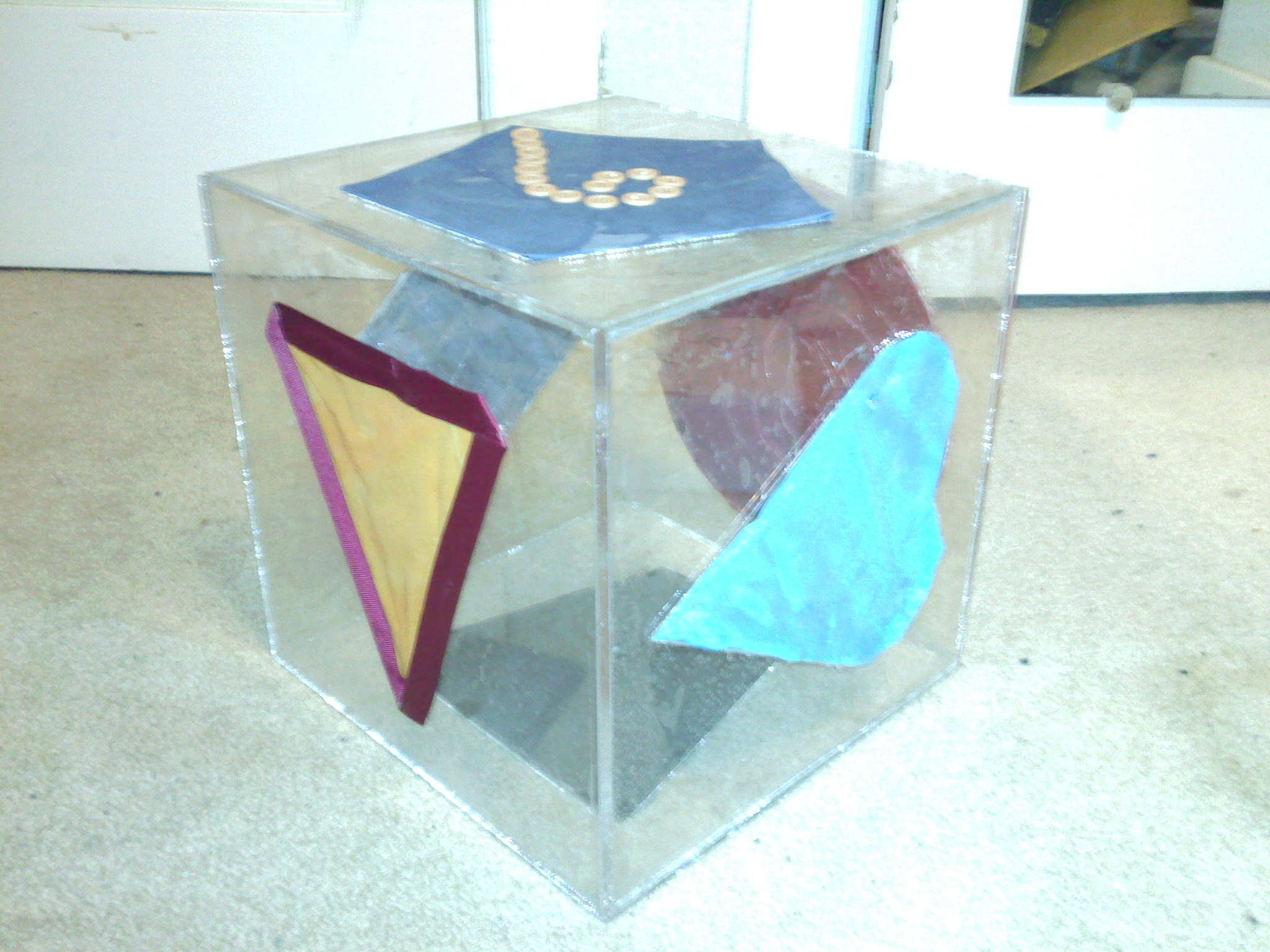
After finishing all of our .dxf files we brought them over to the Chemical Engineering Machine Shop in DH-B211. After turning on the laser cutter and opening the ventilation system, we loaded the 12"x12"x0.1" acrylic sheet into the laser printer (step 1 above). The computer connected to the laser cutter read in the .dxf file and cut on the red lines when you pressed the start button on the printer (step 2). Each piece took about two minutes to finish cutting out. After the piece was finished cutting it was a little wet so we removed it and set it on the workbench to dry (step 3). We cut out all of our pieces in about an hour. To put the pieces together, Larry Hayhurst gave us some acrylic solvent. The solvent "melts" some of the acrylic and bonds it to the other pieces. The solvent worked great in sticking two faces together (i.e. a shape plate and a solid plate). However, we had a really hard time connecting the corners together. After trying two different solvents (both unsuccessful) we decided to use hot glue to attach each of the sides together. The final product that we presented in class (step 4) included the different kinds of materials that we cut out to match the different shapes of our cube.
Improvements Made
Our classmates suggested that we clean up each face of the cube. When we put the solvent on each face to bond them together some of the solvent spilled over onto the workbench. Our piece ended up sticking to part of the bench and we had to pry it off, pulling some grease and part of the workbench with it. As a result, our cube faces look rough. Since the acrylic is clear we can see through to the other side and the back side of the fabric (where it is connected to the cube) is visible. We decided to sand down each side of the cube to help get rid of some of the solvent/oil/workbench stuck to the faces. We also decided to paint each side of the cube after sanding it down.
Rapid Protyping Home | Carnegie Mellon University Home | Back to Top